FIBER LANE
bla
Travel Podcast
fiber optic lane control sign
1.0 Lane Control Signs (General)
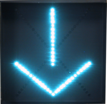
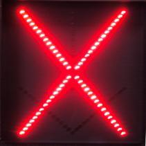
1.1 Standard messages for a lane control sign are a red X, a yellow X or a green arrow (generally pointing down). The sign may come in a one-message format displaying either a red X or a green arrow, or a two-message format to display a red X or a green arrow on the same face, or a three-message to display a red X, yellow X or a green arrow. While these messages are standard, other messages and combinations are available upon request.
1.2 All of the messages listed in 1.1 shall be clearly legible and attract the motorist’s attention under any lighting condition.
1.3 Lane control signs are available in a wide angle version with a 60-degree cone of vision centered about the optic axis.
2.0 One-Sided
2.1 A one-sided sign (one-way) shall have a hinged, extruded aluminum service door on one side only, containing a fiber optic module with the message(s) on it as described in 1.1. This arrangement allows the sign to display the message(s) in one direction.
2.2 The door of a one sided sign, when opened shall allow full access to all of the serviceable components in the sign.
3.0 Two-Sided
3.1 A two-sided sign (two-way) shall have a hinged, extruded aluminum service door in each side containing a fiber optic module with the messages on it as described in 1.1. This arrangement allows the sign to display the messages in both directions and eliminates the need for two single sided signs per location.
3.2 Each door of a two-sided sign when opened shall allow full access to all of the serviceable components in the sign. It is not necessary to service both sides independently.
4.0 Mechanical Construction
4.1 The sign shall be constructed using a weatherproof, aluminum housing consisting of an 8” deep, .125” thick, extruded aluminum body, and a .063” aluminum back. All corners are continuous TIG (Tungsten Inert Gas) welded to provide a weatherproof seal around the entire housing.
4.2 The door shall be constructed of .125” thick extruded aluminum. Two corners are continuous TIG welded with the other two screwed together to make one side of the door removable for installation of the fiber optic module (see 5.0). The door is fastened to the housing on the left by a full length, .040” x 1 ¼” open stainless steel hinge. The door shall be held secure onto a 1” wide by 5/32” thick neoprene gasket by one or more (depending on size) quarter-turn link locks.
4.3 A three-sided visor made of .063” aluminum may be fitted to the door to act as a sunshade and improve the visibility of the message.
4.4 All surfaces of the sign shall be etched and primed in accordance to industry standards before receiving appropriate color coats of industrial enamel.
4.5 All fasteners and hardware shall be corrosion resistant stainless steel. No tools are required for routine maintenance such as a lamp change.
5.0 Fiber Optic Module
5.1 The fiber optic module shall consist of a flat black, aluminum face-plate, .080”: thick with the components described below attached directly to it.
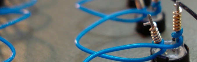
5.2 The glass fiber optic bundles are glued into an end-tip at the termination end and the common assembly at the other end and then ground smooth and optically polished to ensure maximum light transmission through the bundle.
5.3 The end-tip holder, of black Delron is inserted into a punched hole in the face-plate and mechanically held in place by a plated snap ring on the interior. The assembly, when installed on the face-plate shall not protrude more than 5/16”.
5.4 The color filter provides the message color and is made of tempered, optically correct glass and is in conformance with I.T.E. specifications. It is mounted with four screws between the common assembly and lamp. Color filter can be changed in the field without removing the module from the housing.
5.5 Each message is illuminated by two light sources and the glass bundles are arranged so that in the event of a failure of one of the light sources the other shall continue to provide a legible message by lighting every other point in the message. (Bifurcation of each point between the two light sources is available on one- or two- message signs for fail-safe purposes at an additional cost). No color shall appear in the output points when deactivated, regardless of ambient light conditions.
6.0 Electrical
6.1 Type ENL lamps shall be used to illuminate the messages. They shall be 42 watt, 10.8 volt with a rated life of 8,000 hours. Two lamps shall be used per message to provide fail-safe operation in the event of lamp failure.
6.2 Step-down transformers shall be used to reduce the incoming 120 volts A.C. to 10.8 volts A.C. The transformers shall be rated at 48.5 volt-amps and have “A” class insulation and weatherproofing. A separate transformer shall be used with each lamp to provide further burnout protection.
6.3 A barrier type terminal strip is provided for electrical connection of field wires.
6.4 The power consumption per message shall be less than 90 watts with both lamps illuminated. The sign shall be capable of continuous operation over a range of temperatures of –35 degrees to +165 degrees Fahrenheit.
Lighting the way
Traffic Signs Inc.
Fluorescent:
NIRF: